Virtual Sources
Virtual sources represent objects that can be moved around the 3D Venue. They are made of one or more (stereo, multichannel) audio source(s), and can be freely positioned around the audience. Those sources include an acoustic simulation module (with reverberation), that can be automatically controlled by the position of the source.
There are three formats for virtual sources.
Mono sources can be positioned anywhere around the audience.
Stereo sources are composed of two Mono sources, their spacing is set by the Stereo Width. The position of a stereo object is set by its center and its Stereo Width.
Multichannel sources are composed of multiple Mono sources. Their layout can be manually adjusted, but will correspond by default to ITU standards.
Inspector Settings
Header Section
Virtual Sources all share the same Header settings documented in the Introduction for Sources. But Stereo and Mono Sources have some additional parameters: position, and stereo width.
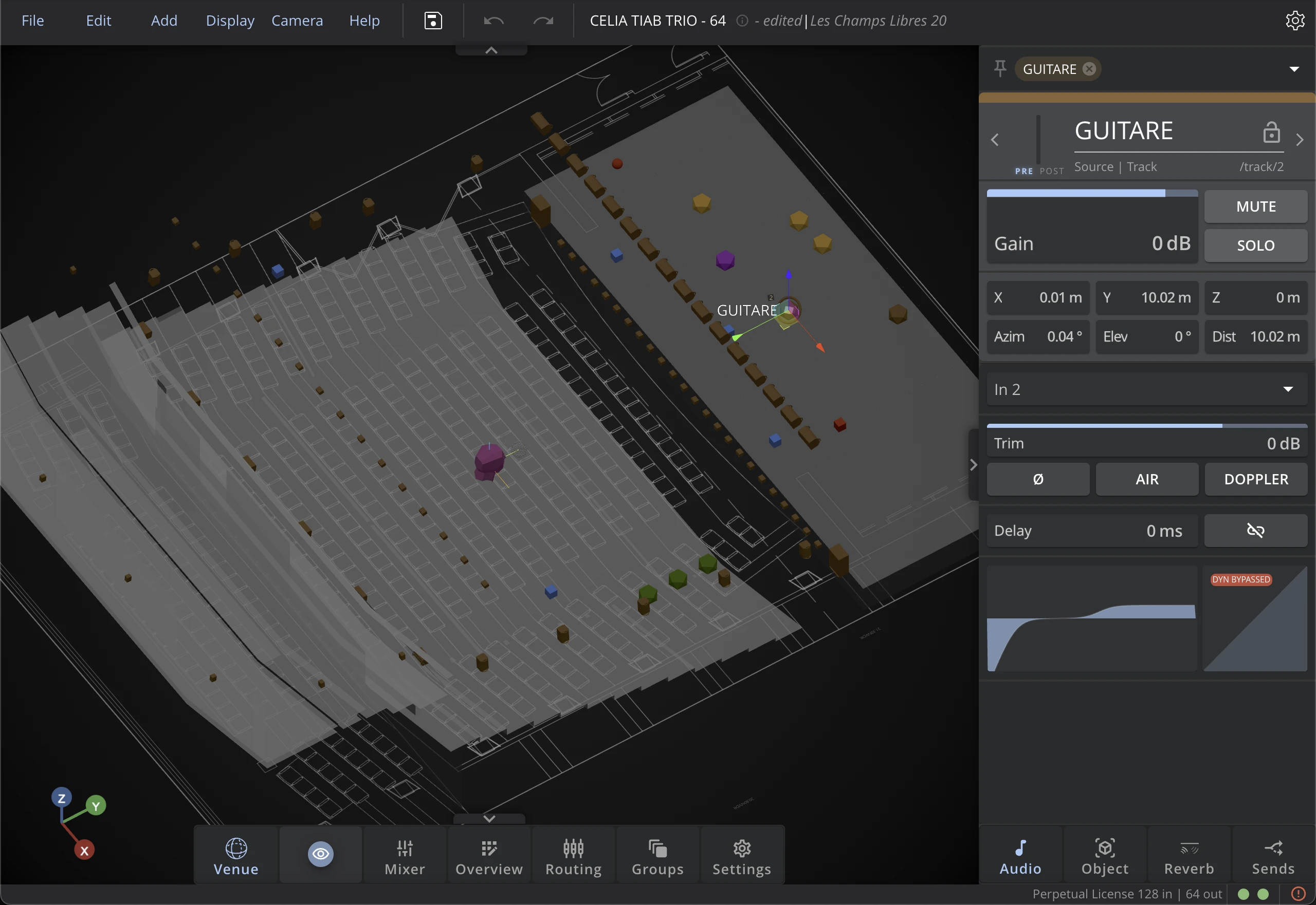
Position
Move or position the source directly in the 3D Venue, or by entering its coordinates. Two coordinates systems are available: see Coordinates Systems for more detail.
Width
The Stereo Width sets the total spreading angle of the left and right channels around the center. For example, the default 30° width sets the left channel at -15° and the right channel at +15° around the center displayed in the 3D Venue.
Tab Section (Mono & Stereo Sources)
Audio Tab
Doppler
Activate this option to simulate the Doppler effect when a source is moved, causing a pitch change.
Air
Activate this option to simulate the air absorption filtering with distance.
Phase
Activate this option to inverts the signal's phase.
Delay
This parameter is common to all sources. It is therefore documented the Tab section of parameters common to all sources.
EQ | Dynamics
This parameter is common to all sources. Check theEqualizer page and Dynamics page for more details.
Object Tab
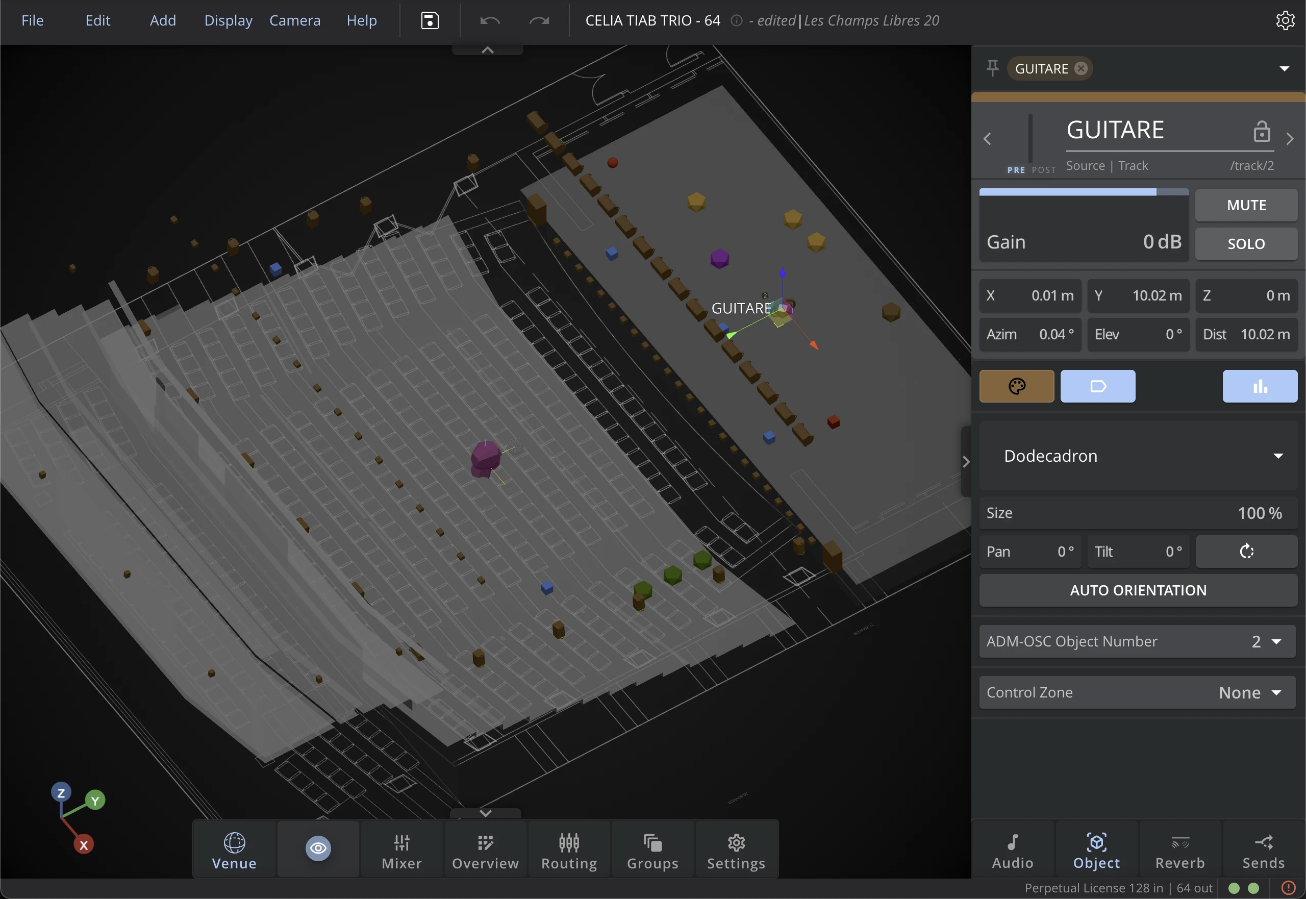
Color
You can change your element's color. To learn more about it, check the Color parameter in the Inspector page.
Label Visibility
Click on this button to display or hide the element's label in the 3D Venue.
3D File
Like for loudspeakers, the 3D model of the source can be changed to help identifying it in the 3D Venue. Along with changing the source color, it can help you identify sources more easily in the 3D Venue.
Size
The individual display size of each source can be adjusted with the Size factor. When the scale is set at 2, the displayed size will be twice as big.
Don't forget that you can adjust the size of all objects from the Display menu in the options bar.
Orientation
The orientation parameters only set the display of the 3D model. It has not impact over sound.
See the 3D orientation section of the coordinates system page for more details.
Auto Orientation
Enable Auto Orientation to make the source's 3D model automatically face a chosen reference point. When active, the Pan and Tilt values become derived from the selected target and update in real time whenever that target is moved.
On Virtual Sources, Auto Orientation is purely visual - it only affects the 3D model display in the 3D Venue and has no impact on the sound produced.
Target
Choose what the source's 3D model orients toward when Auto Orientation is enabled:
- Origin - the center of the 3D Venue (default).
- Bus N - the reference point of any existing bus. The 3D model re-orients automatically when that bus's reference point is moved.
The Target selector only appears when Auto Orientation is enabled. If the selected bus is later deleted, the target falls back to Origin automatically.
ADM Object Number
Use this parameter to set the ADM Object Number corresponding to its iteration in ADM-BWF file used to control this source over the ADM-OSC protocol.
Control Zone
Use this parameter to set the Control Zone of the source, which is the area in which the source will be controlled external devices (OSC, ADM-OSC, or Yamaha Consoles). Check the External Controls section for more details.
Reverb Tab
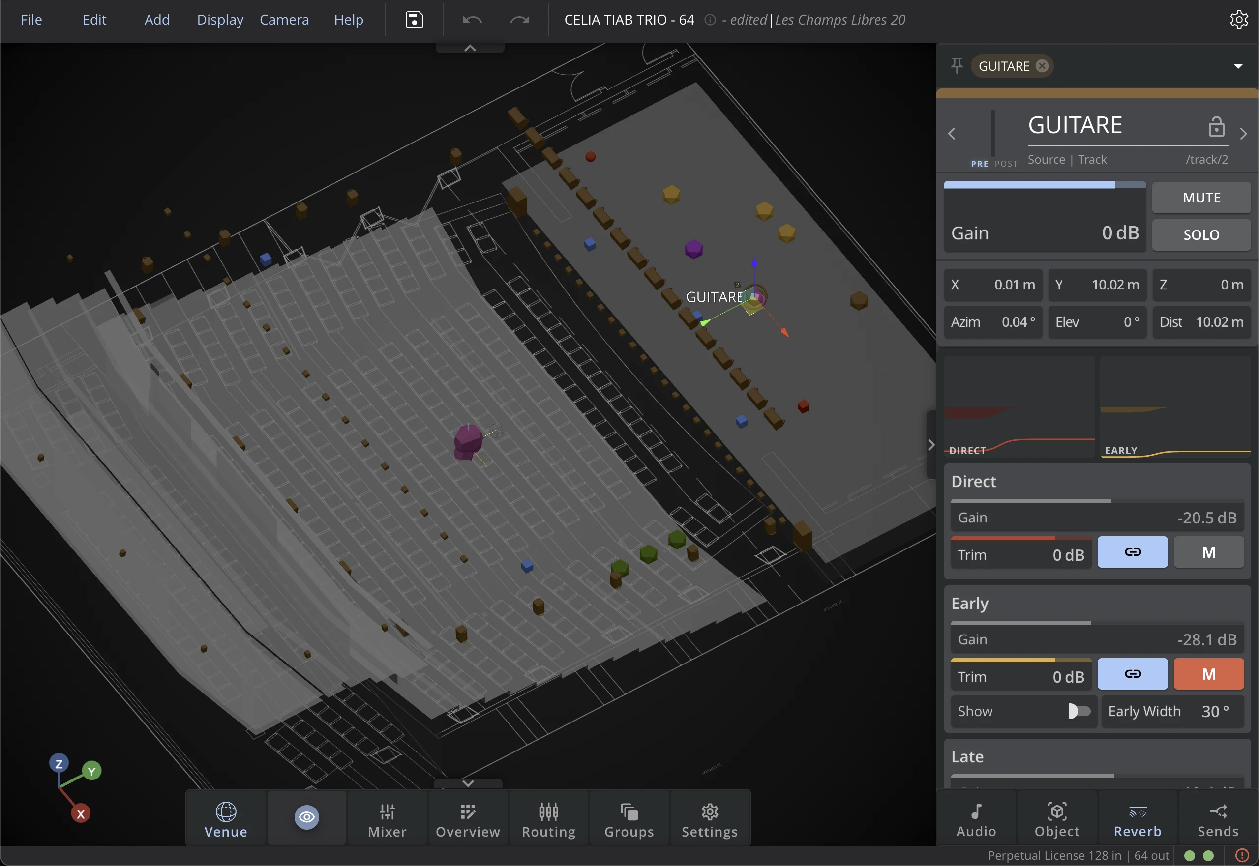
Direct, Early, and Reverb
Check the Reverb page for more information on source reverb settings.
Sends Tab
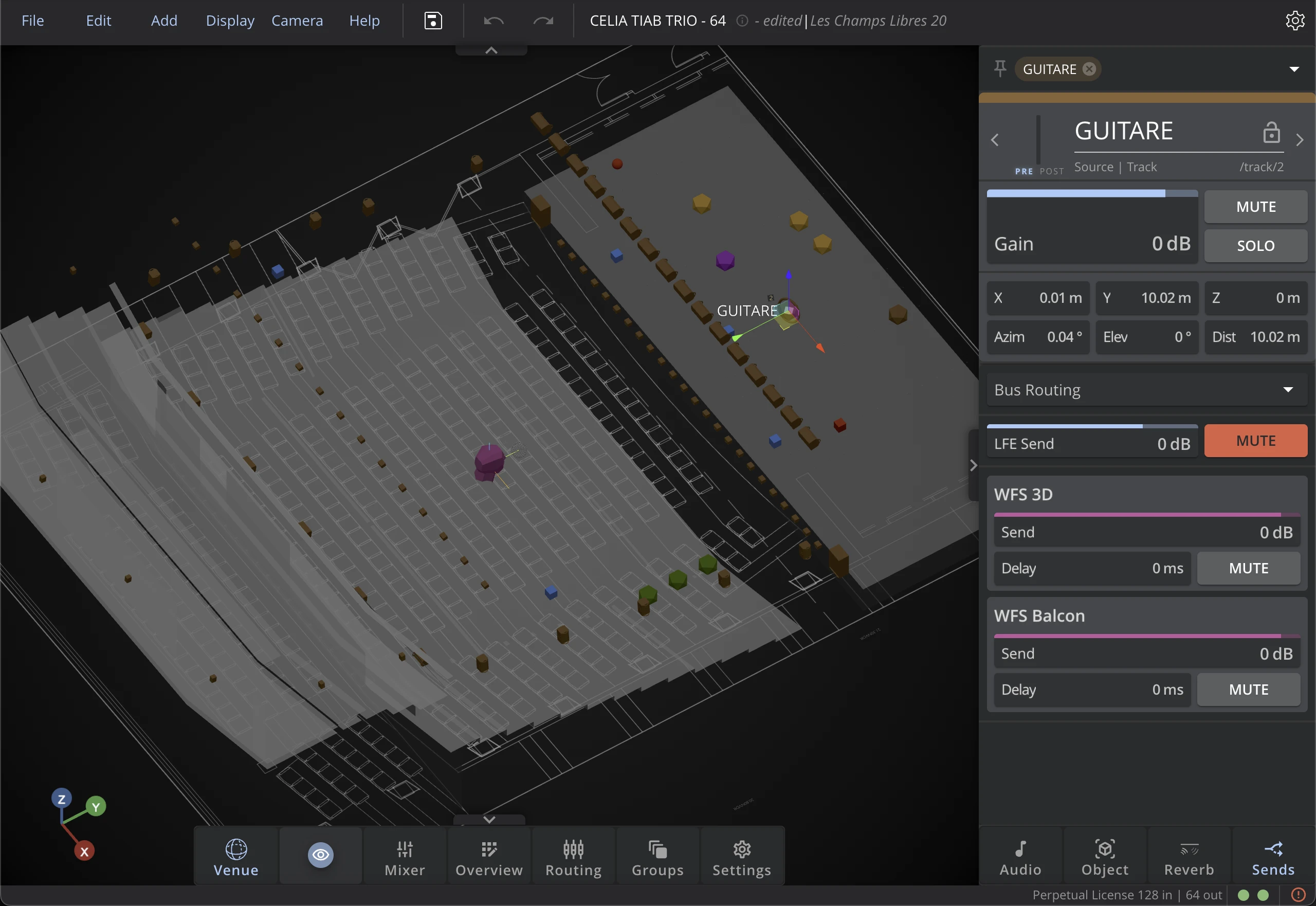
This tab is identical for all Sources. Check the Dedicated Section to learn more about it.
Multichannel
Position
The multichannel object can only be moved with the AED Distance coordinate. The layout can be edited with the Channels Parameters window.
Multichannel Parameters
The Object, Reverb, and Sends tabs are identical to Mono and Stereo Sources. However, the Audio tab is slightly different. Doppler, Air, and Phase are not available as Multichannel Sources are not meant to be in motion.
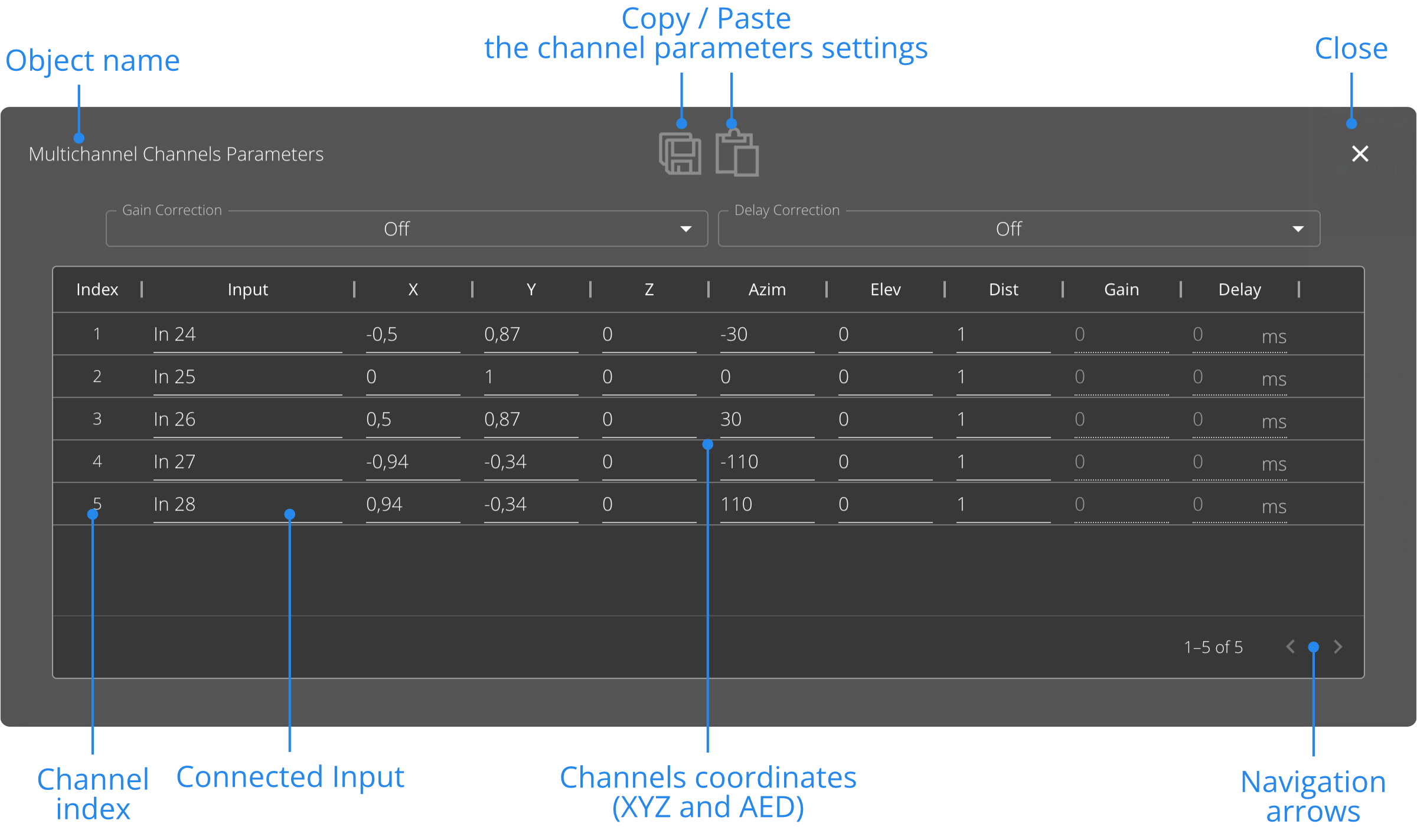
Use the Channels Parameters window to the position, gain and delay alignment of the individual channels of a Multichannel object.
Input
This field indicates which input is connected to each channel composing the Multichannel object. If you need to connect a channel to another input, use the Routing view.
Channels Coordinates
Use the XYZ and AED columns to adjust the position of the channels.
The values entered in these fields correspond to the channels positions when the Multichannel object AED Distance coordinate is set to 1 meter.
If your Multichannel is set to another distance, the resulting distance of the channels will be multiplied by that AED Distance.
Gain & Delay correction
The gain and delay corrections allow you to time-align and level-align each channel individually.
Three modes are available for both gain and delay correction, and can be selected from the two drop-down menus at the top:
Off
It is the default setting. This will disable the gain or delay alignment.
Manual
The manual mode will enable manually setting the gain or delay values.
Auto
Auto mode will let HOLOPHONIX compute the gain and delay values for a perfect phase and level alignment at the center of the Multichannel object.
Gains and delays are computed as if all the channels were placed on a circle or a sphere. By evaluating the distance between the virtual position on a circle and the real object position, HOLOPHONIX determines the delay and gain attenuation.
Channels that are the closest to the center will receive a maximum delay and gain attenuation, whereas the farthest channels will receive no delay or gain attenuation.